Wed 24 Jun 2026 | 14:13 Beijing
Integrated Solutions
Product search


HIGH FREQUENCY PIPE WELDER>
HIGH FREQUENCY PIPE WELDER> Buildup & Models

Buildup & Models

 |
 |
SOLID STATE HIGH FREQUENCY WELDER
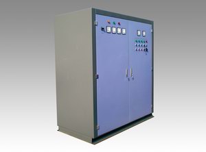
1. Switch Rectifying Cabinet
The switchgear and the rectifier are integrated here into one switch rectifying cabinet, which enables both the switchgear function, and the rectifying control function of the solid state H. F. welders.
Incoming MCCB (molded case circuit breaker), incoming current meter, incoming voltage meter (switchable type), and incoming voltage indicator.
3-phase full-control thyristor rectifying bridge enables power regulation.
Smoothing reactor, smoothing capacitors and filter to increase the smoothing coefficient.
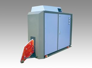
2. Inverter Output Cabinet
The inverter circuit consists of MOSFET single-phase inverter bridges connected in parallel, with the power of each bridge designed as 120kW/60kW. Thus the power is accumulated in the style of building blocks. Each inverter board is designed into the drawer structure with slides on both sides, which facilitates installation and repair.
The powers is combined through several transformers (called matching transformers) and by direct resonance between the tank circuit resonant capacitors (low voltage) and the inductor, it is transferred to the welding unit via the bus lead, and no welding transformer is needed here.
Sealed cabinet with the air conditioner installed on the top of it.
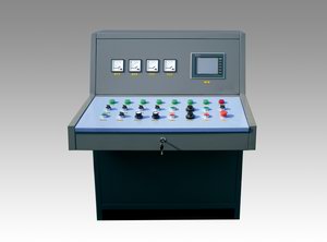
3. Central Operator Console
The central operator console allows remote operation and power regulation of the welder. It is equipped with HMI (human/machine interface), indicates DC voltage and DC current of the H. F. welder, and armature voltage and field voltage of the motors of the forming and sizing mill. Design of the central operator console is customized according to different types and quantities of the motors. The power-speed closed loop control / automatic power-speed control function is optional.
4. Mechanical Adjustment Device
2-D mechanical adjustment device: applicable for solid state induction welders only. The inverter output cabinet is installed on the adjustment device, so the position of the inductor can be manually adjusted.
3-D mechanical adjustment device: applicable for both solid state induction welders and solid state contact type welders. The inverter output cabinet is installed on the adjustment device, so the position of the inductor can be adjusted manually or electrically.
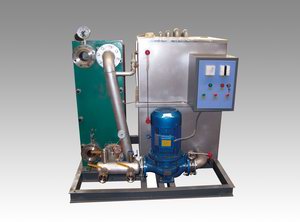
5. Closed Loop water cooling system
The GPKL-II cooling system adopts a closed cooling tower, in which the blowers and water spraying hoses on the top will cool the soft water already pumped into the finned tubes. The spraying water (normally purified tap water) is accumulated at the bottom of the cooling tower. It is pumped into the spraying hoses and sprays onto the surface of finned tubes—Part of the spraying water will vaporize when it is falling, thus carries away some heat and partially lower the temperature of the soft water circulating inside. The vapor goes up due to the blower and intensifies the cooling effect when it passes the finned tubes again, and finally goes out of the cooling tower. The other part will fall through the PVC heat exchange layer which is located under the two blowers and above the finned tubes, thus gets cooled by the cold air passing by and finally joins the spraying water at the bottom.
 |
 |
Models for solid state H. F. welders
|
Output Power
|
DC Power
|
Welder Model
|
Rated Voltage
|
Rated Current
|
Frequency
|
E. Efficiency
|
|
60kW
|
80kW
|
GGP60-0.5-H
|
450V
|
180A
|
450~500kHz
|
≥ 85%
|
|
100kW
|
120kW
|
GGP100-0.45-H
|
450V
|
270A
|
400~450kHz
|
≥ 85%
|
|
150kW
|
180kW
|
GGP150-0.4-H
|
450V
|
400A
|
350~400kHz
|
≥ 85%
|
|
200kW
|
240kW
|
GGP200-0.35-H
|
450V
|
530A
|
300~350kHz
|
≥ 85%
|
|
250kW
|
300kW
|
GGP250-0.35-H
|
450V
|
670A
|
300~350kHz
|
≥ 85%
|
|
300kW
|
360kW
|
GGP300-0.35-H
|
450V
|
800A
|
300~350kHz
|
≥ 85%
|
|
400kW
|
480kW
|
GGP400-0.3-H
|
450V
|
1070A
|
200~300kHz
|
≥ 85%
|
|
500kW
|
600kW
|
GGP500-0.3-H
|
450V
|
1330A
|
200~300kHz
|
≥ 85%
|
|
600kW
|
720kW
|
GGP600-0.3-H
|
450V
|
1600A
|
200~300kHz
|
≥ 85%
|
|
700kW
|
840kW
|
GGP700-0.25-H
|
450V
|
1870A
|
150~250kHz
|
≥ 85%
|
|
800kW
|
960kW
|
GGP800-0.25-H
|
450V
|
2130A
|
150~250kHz
|
≥ 85%
|
|
1000kW
|
1200kW
|
GGP1000-0.25-H
|
450V
|
2670A
|
150~250kHz
|
≥ 85%
|
|
1200kW
|
1440kW
|
GGP1200-0.25-H
|
450V
|
3200A
|
150~250kHz
|
≥ 85%
|
Notes: The frequency can reach 800kHz if special design is requested by the customer.